
How to Connect Legacy PLCs to a Modern SCADA System with Ignition
How to connect a legacy PLC to a modern SCADA system with Ignition, first identify the controller’s model, firmware and communication interface. Then choose the shortest supported path into Ignition’s OPC UA layer: a native device driver where one exists, or a third-party OPC UA server or protocol gateway where it does not. After the connection is configured, build the tags, map the addresses and validate every value against the PLC program before screens, alarms or historians depend on them.
“Legacy” has no formal definition. In this article it means a controller that still runs production but is no longer a current product line, often lacks native OPC UA, and is usually addressed with older, register- or file-based protocols. Typical examples are PLC-5, SLC 500, MicroLogix, Siemens S7-300/400 and anything that speaks Modbus.
What Does It Mean to Connect a Legacy PLC to SCADA?
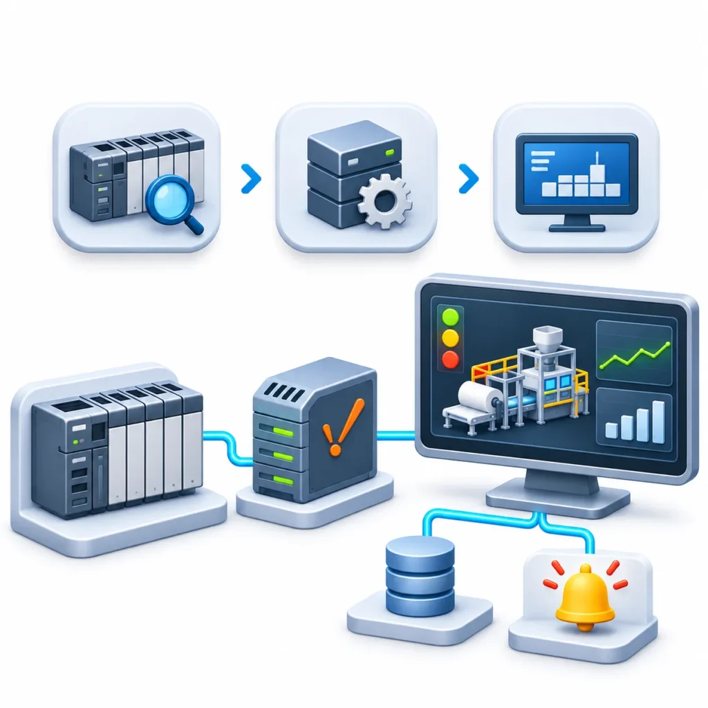
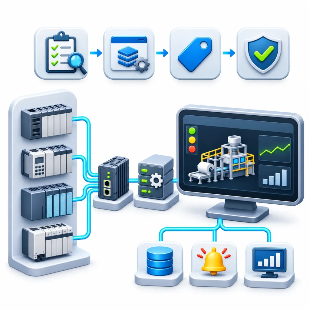
A PLC executes control logic: it reads inputs, runs the program and drives outputs. SCADA supervises: it collects data from controllers, displays it, raises alarms, stores history and lets operators issue commands. Connecting the two means SCADA reads (and, where permitted, writes) PLC data over a communication protocol, without changing the control logic that runs the machine.
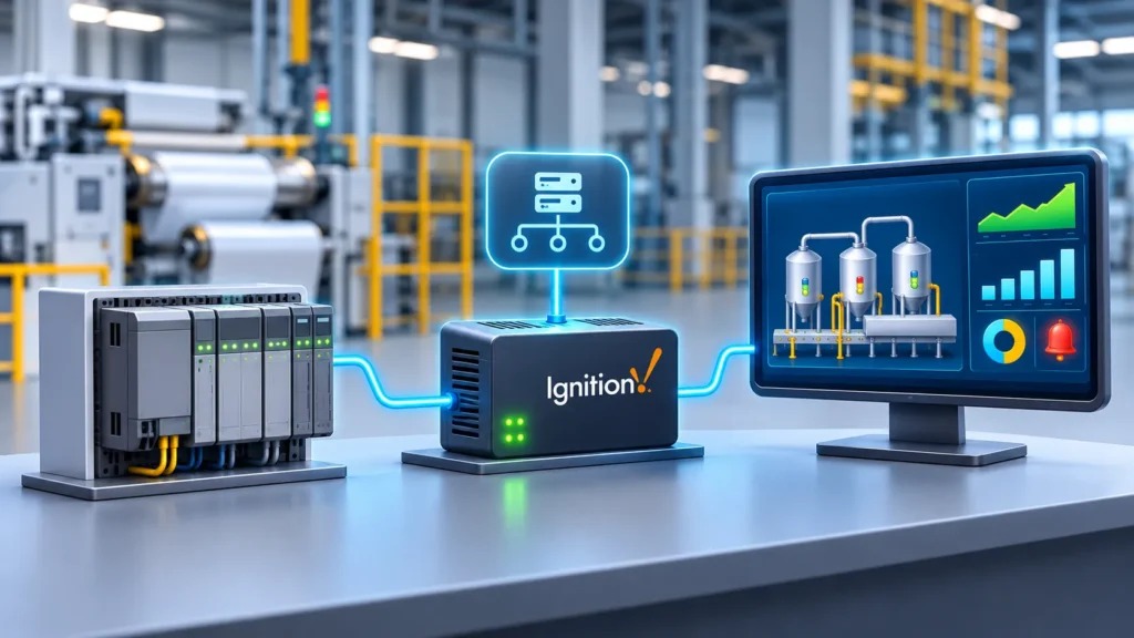
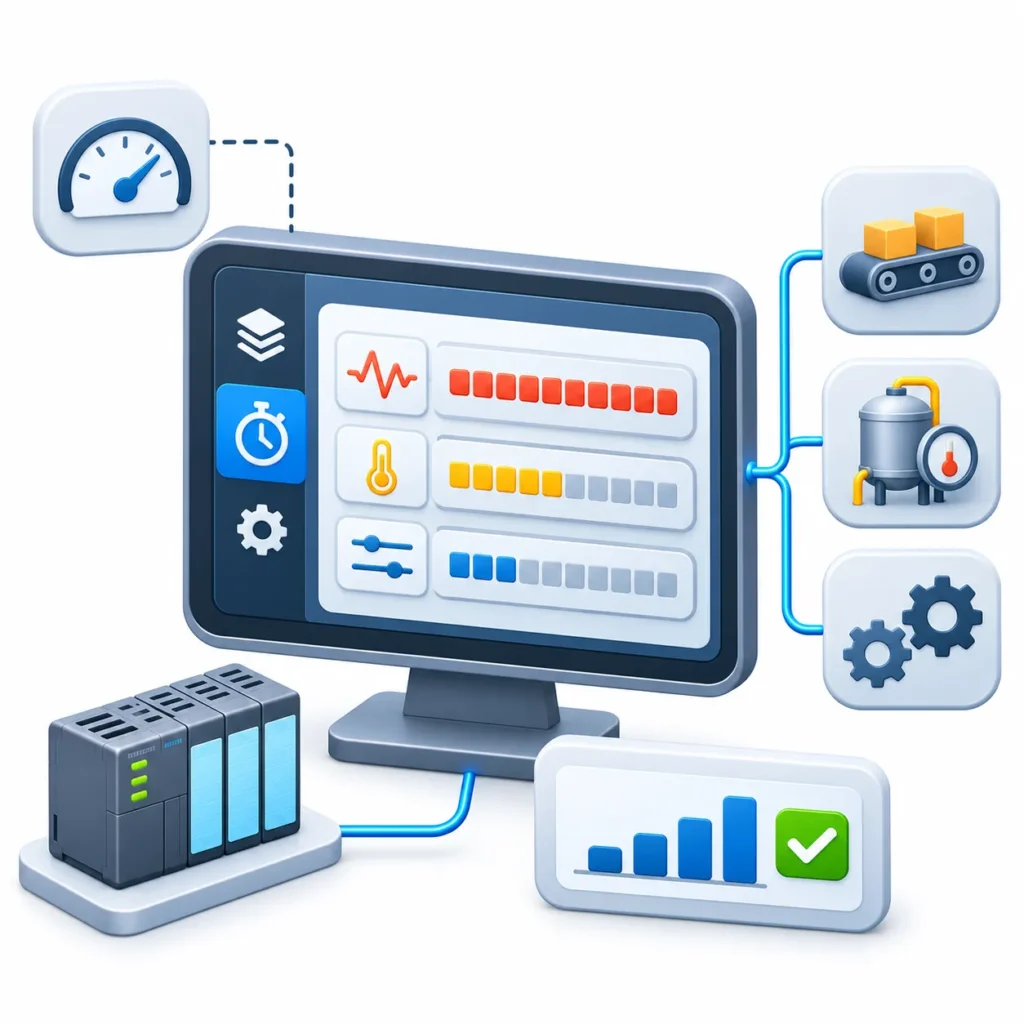
Ignition is an industrial application platform from Inductive Automation. With its OPC UA module installed, the Ignition Gateway acts as an OPC UA server that hosts device drivers, so data collected from PLCs becomes available to other Ignition modules and to external OPC UA clients. Ignition also includes OPC UA client functionality, so it can connect to external OPC UA servers.
Analysis: Wrapping a legacy PLC with SCADA is often the lowest-risk way to modernize. The controller, its validated program and its wiring stay untouched, while visibility, alarming and data collection move to a current platform. Replacing the PLC is a separate decision with different cost, downtime and revalidation implications.
Reference Architecture
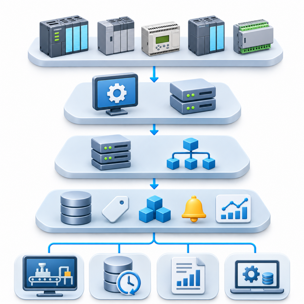
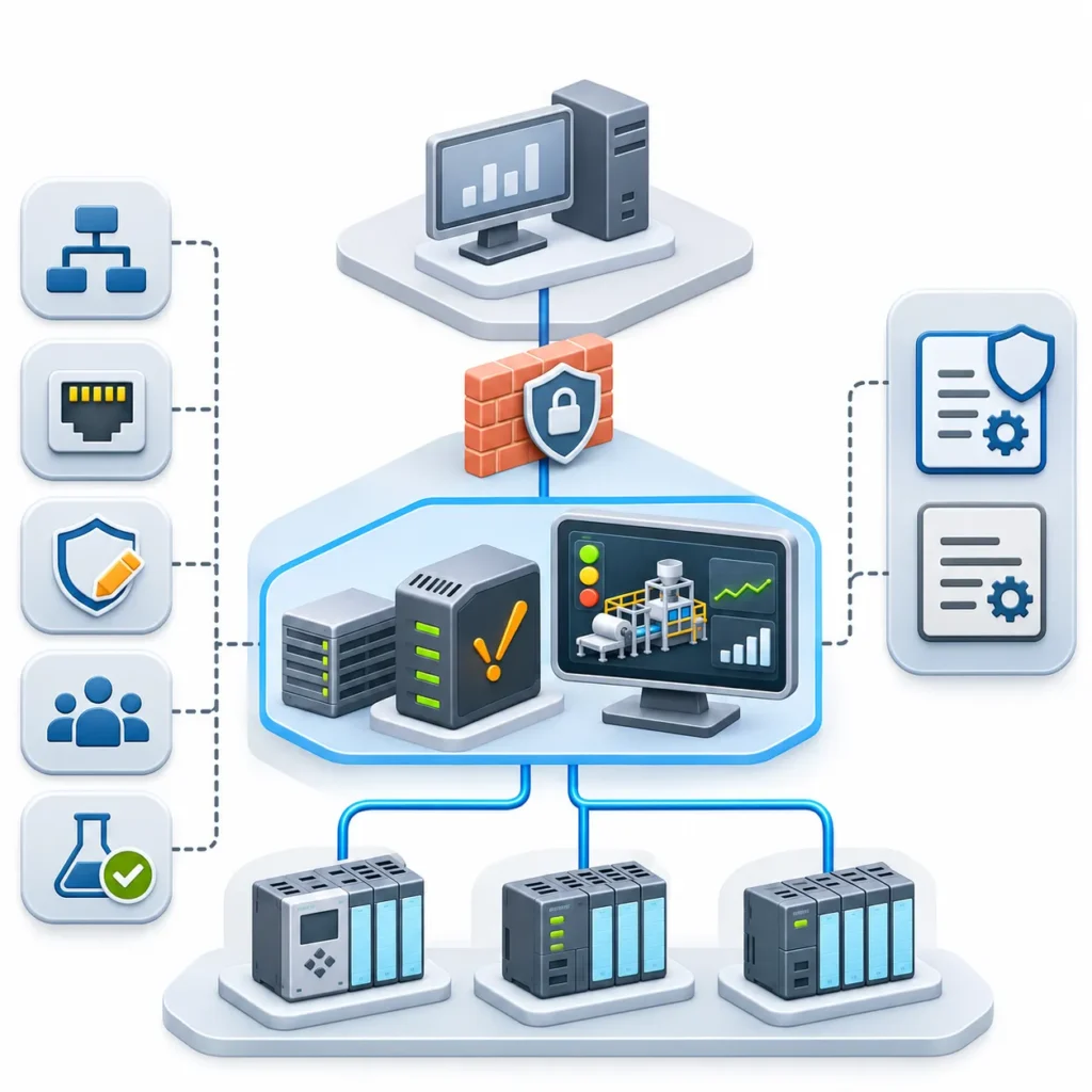
Each layer has a distinct job:
- Legacy PLC: runs control logic and holds process data in registers or data files.
- Device driver: speaks the PLC’s native protocol and translates addresses into OPC UA items.
- OPC UA server: presents those items in a vendor-neutral way to Ignition and to other OPC UA clients.
- Tag system: gives each value a name, data type, scaling, alarm limits and optional history.
- Clients and integrations: screens, trends, reports and downstream systems consume tags rather than raw addresses.
Keeping these layers separate means a screen never needs to know that a value comes from register 40001 or a data file element. If the PLC is later replaced, the tag’s source changes, not every screen.
Step 1: Inventory and Classify the PLC
Item to record | Why it matters |
Exact model and processor series | Determines whether a native driver exists |
Firmware or revision | Driver support can depend on firmware level |
Communication ports | Ethernet, serial, DH+ or another network decides the path |
Protocol and addressing model | Symbolic names, data-file addresses and absolute offsets behave differently |
Program and data map | Tells you what each address means |
Network location and ownership | Needed for firewall rules and change approval |
Production criticality | Sets how cautious reads, writes and scan rates must be |
Before opening the Gateway, record what you are connecting to. Most failed legacy integrations trace back to guessing at one of these items.
Step 2: Choose the Connection Path
Situation | Typical path | Main consideration |
Allen-Bradley PLC-5, SLC 5/05 or MicroLogix | Ignition Allen-Bradley driver | File-based addressing, not symbolic tags |
Siemens S7-300 or S7-400 | Ignition Siemens driver | Absolute addressing only |
Device supporting Modbus | Modbus TCP, RTU over TCP or RTU driver | Register map must be documented or discovered |
Brand or protocol without an Ignition driver | Third-party OPC UA server (for example, Kepware) | Extra software, licensing and certificate trust |
OPC DA (DCOM) server | OPC COM module bridging to OPC UA | DCOM is hard to configure and insecure over networks |
Serial-only controller | Gateway or protocol converter, or an added Ethernet module | Engineering judgment; verify the specific hardware |
The decision rule is simple: use a native driver if Ignition documents your exact model, use a standards-based OPC UA server if it does not, and add hardware only when the controller has no usable network interface.
Legacy Platforms Ignition Documents
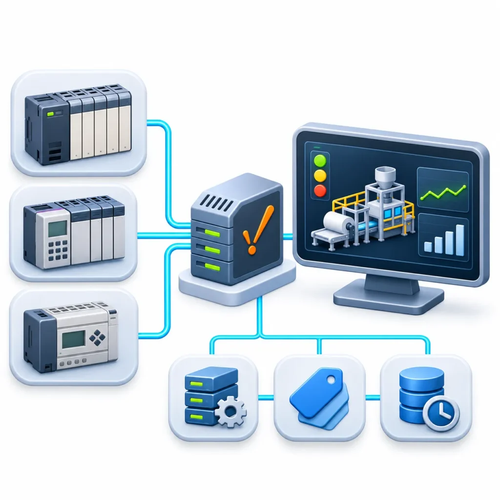
Allen-Bradley PLC-5, SLC and MicroLogix
Ignition’s OPC UA module includes Allen-Bradley drivers for EtherNet/IP devices. The documented device list includes MicroLogix 1100, 1200, 1400 and 1500 series, PLC-5 over Ethernet and SLC 5/05 over Ethernet. Separate legacy drivers cover ControlLogix and CompactLogix processors on firmware v20 and earlier, while the Logix driver targets firmware v21 and later.
For PLC-5, Ignition’s documentation lists connection through PLC-5 L/20E, L/40E and L/80E processors over EtherNet/IP, and any PLC-5 on DH+ through a 1756-DHRIO module in a ControlLogix chassis, using an Allen-Bradley connection path and the processor’s DH+ node number. The documentation also notes that ASCII data types from PLC-5 devices are not supported by this driver.
MicroLogix, PLC-5 and SLC controllers do not use symbolic tag names. Their data is addressed by file and element, so tags are created manually or imported rather than browsed.
Siemens S7-300 and S7-400
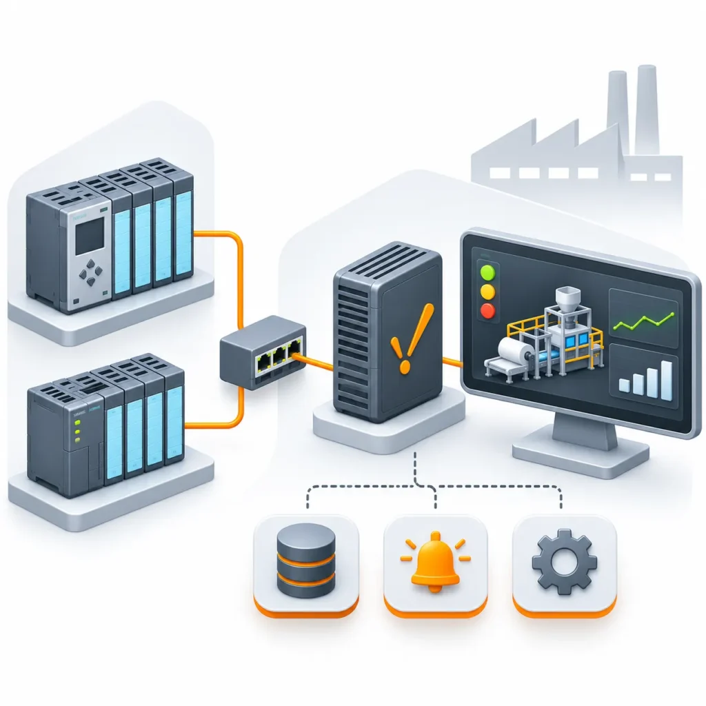
Ignition connects to S7 controllers over TCP/IP using the S7 protocol. The S7-300 and S7-400 drivers support absolute addressing only, and the default port is 102. The Siemens Enhanced driver also supports S7-300 and S7-400, but only with absolute addressing; browsing and symbolic access apply to S7-1200 and S7-1500 devices. Absolute offsets mean that adjacent words overlap by byte, so two consecutive, non-overlapping words are addressed at offsets 0 and 2, not 0 and 1.
If the plant also contains S7-1200 or S7-1500 controllers, note that their data blocks need optimized block access turned off and PUT/GET access permitted for absolute addressing. Treat that as a security decision, not a checkbox.
Modbus Devices
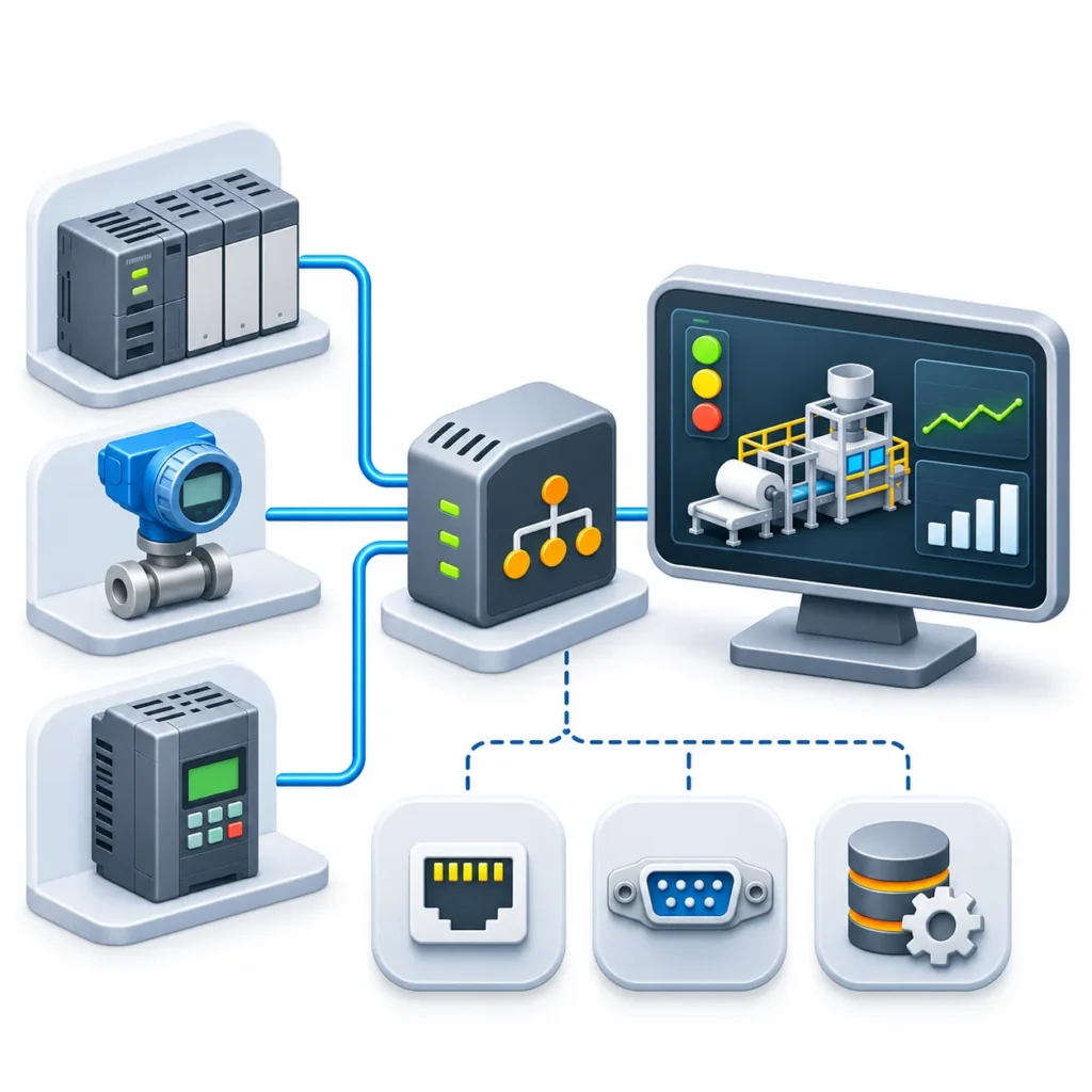
Ignition’s Modbus driver connects to devices that support Modbus over Ethernet or serial. The Gateway offers Modbus TCP for native Modbus TCP/IP devices, Modbus RTU over TCP for devices or gateways that encapsulate RTU messages in TCP packets, and Modbus RTU for serial communication. Only one Modbus device should be added per IP address in Ignition’s device list, which matters when a serial-to-Ethernet gateway fronts several slaves.
Connecting is easy; addressing takes the time. A holding register is referenced by a simple item path such as the device name followed by HR1, and an address map lets you drag and drop tags the way you would with a browsable device.
Third-Party OPC UA and OPC DA Sources
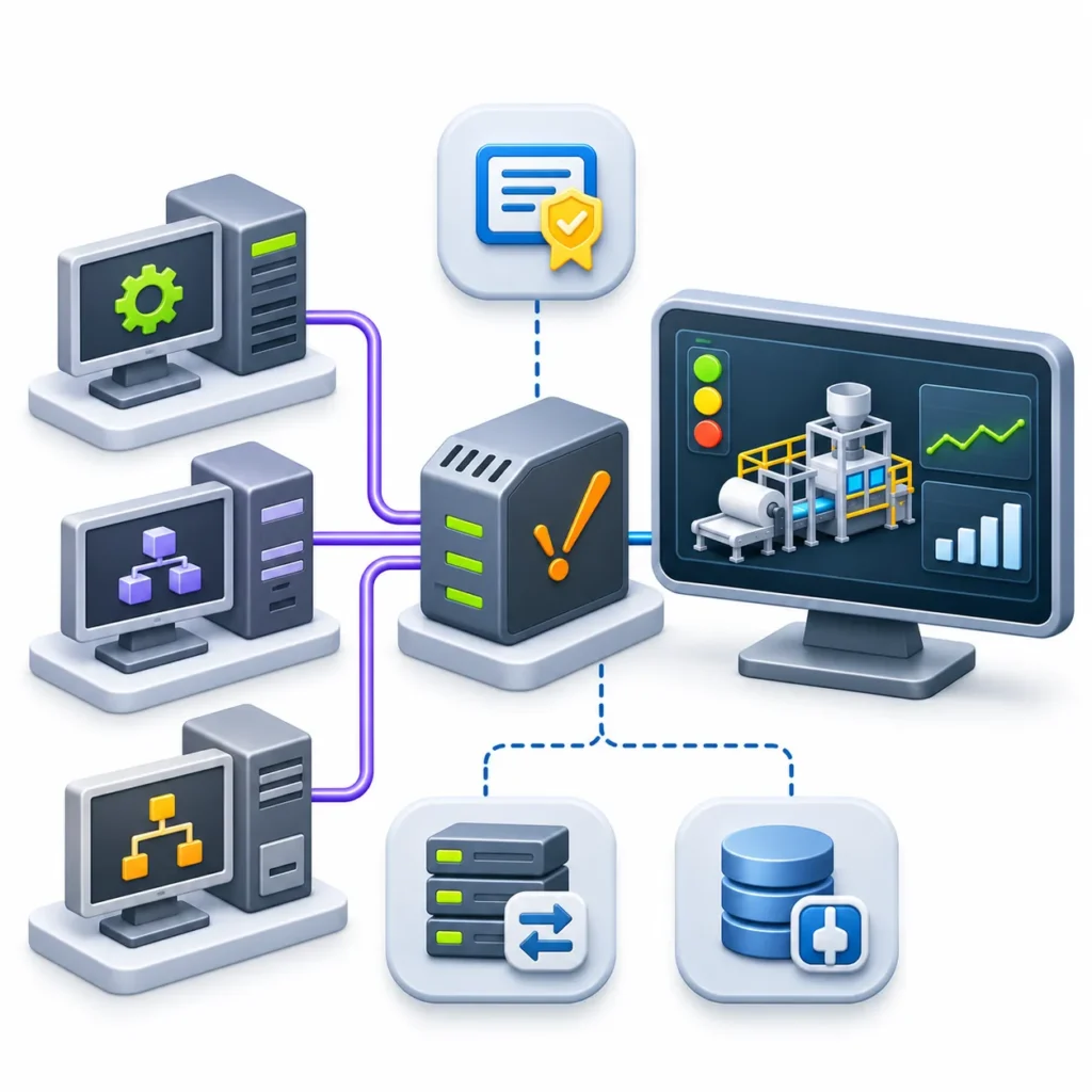
Ignition can connect, as an OPC UA client, to third-party servers such as Kepware, to another Ignition Gateway, or to software gateways that translate protocols into OPC UA. Ignition does not automatically approve third-party server certificates, so plan for certificate trust during commissioning. For older OPC DA servers, the OPC COM module bridges DCOM-based OPC DA to OPC UA, although Ignition’s documentation recommends OPC UA wherever possible.
Step 3: Prepare the Network and Security
Legacy PLC protocols were designed for isolated plant networks. Many have no meaningful authentication or encryption, so the network design carries the security burden.
- Segment the path. Place the Ignition Gateway and the controllers in a controlled OT zone, and allow only the required traffic between them.
- Allow-list ports. Open only what the driver needs, such as port 102 for S7 or the Modbus TCP port the device uses.
- Start read-only. Disable or restrict writes until the data has been validated. The Modbus driver, for example, exposes an Allow Write setting.
- Control who can write. Use Ignition’s role-based security so only authorized roles can send commands to a PLC.
- Separate test from production. Connect first to a spare or offline controller if one exists.
NIST SP 800-82 Revision 3, finalized in September 2023, is the standard U.S. guide for securing operational technology and includes tailored security baselines for OT systems. Use it, or IEC 62443, as the reference for segmentation and access decisions rather than improvising.
Step 4: Configure the Device Connection
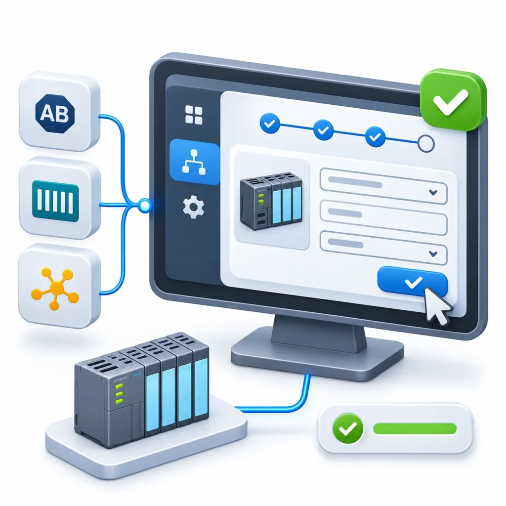
The sequence is similar across drivers:
- In the Gateway web interface, open Connections > Devices > Connections.
- Select Create Device Connection and choose the driver, such as Allen-Bradley PLC5, Siemens S7-300 or Modbus TCP.
- Enter a clear device name and the controller’s IP address as the hostname. For serial Modbus, enter the serial port instead.
- Adjust connection-specific fields, such as the connection path for PLC-5 on DH+ or the port for Siemens.
- Save the connection and confirm the status moves from Disconnected to Connected.
Choose device names carefully. They become part of every tag path, and renaming later means rework.
Step 5: Build and Organize Tags
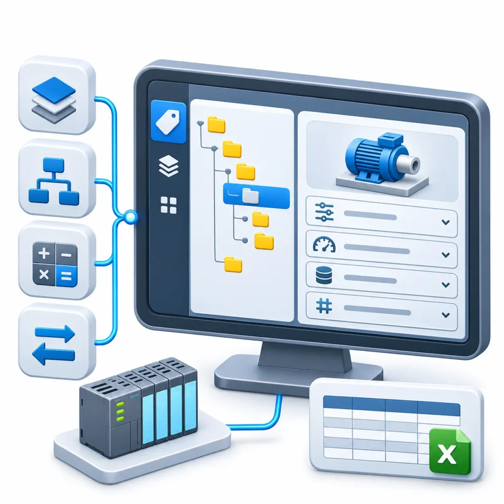
Tags turn raw addresses into usable plant data. For a legacy PLC, you typically create them manually or bulk-import them from a spreadsheet.
- Use a consistent hierarchy, for example site, area, line, equipment, signal.
- Use UDTs (user-defined types) for repeated equipment such as motors or conveyors, so the structure is defined once.
- Record scaling and units. Raw integers from a PLC are often scaled; document the engineering range in the tag, not in someone’s memory.
- Check data types and byte order. A 32-bit value spread across two Modbus registers can differ by device in word order, which is a common cause of values that look plausible but are wrong.
- Keep a tag-to-address register (a spreadsheet is enough) so the PLC program, the tag list and the screens stay traceable to each other.
Step 6: Validate Before You Trust the Data
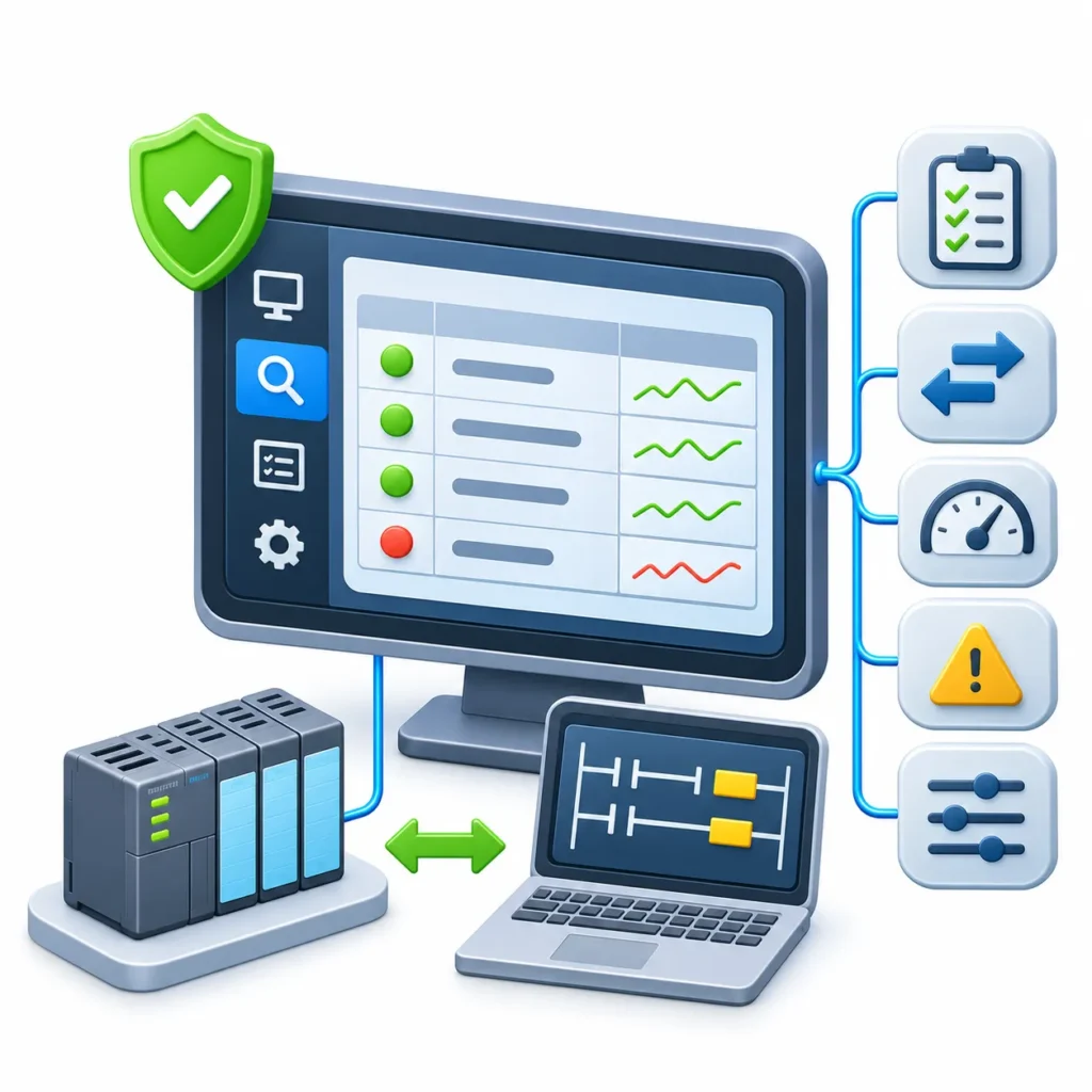
Validation is where integrations earn their credibility.
- Browse and read live values with the OPC Quick Client, which Ignition provides to inspect the OPC UA server and verify that values are arriving.
- Compare against the PLC. Check a sample of values against the controller’s programming software while the process is in a known state.
- Test edge cases. Check negative numbers, maximum values, bit-level flags and string fields.
- Test failure behavior. Unplug the cable or stop the device and confirm that the tag quality turns bad rather than leaving a stale value displayed as good.
- Test writes last, and only on non-critical points with operations present.
Ignition’s Modbus documentation suggests creating a few tags manually and adjusting connection settings until the values are correct before building out the full tag set. The same discipline applies to every driver.
Step 7: Manage Polling Load
Analysis: Older CPUs have limited communication capacity, and scanning every tag at the fastest rate can slow the controller’s communications and make data less reliable, not more. Group tags by how fast they genuinely change: fast for machine states, slower for temperatures and counters, on-demand for configuration values.
Driver settings help. The Modbus driver exposes limits such as maximum registers per request and a span-gaps option that reads across unused addresses to reduce the number of requests. Fewer, larger requests are usually gentler on a legacy device, but a device that rejects large reads needs smaller ones.
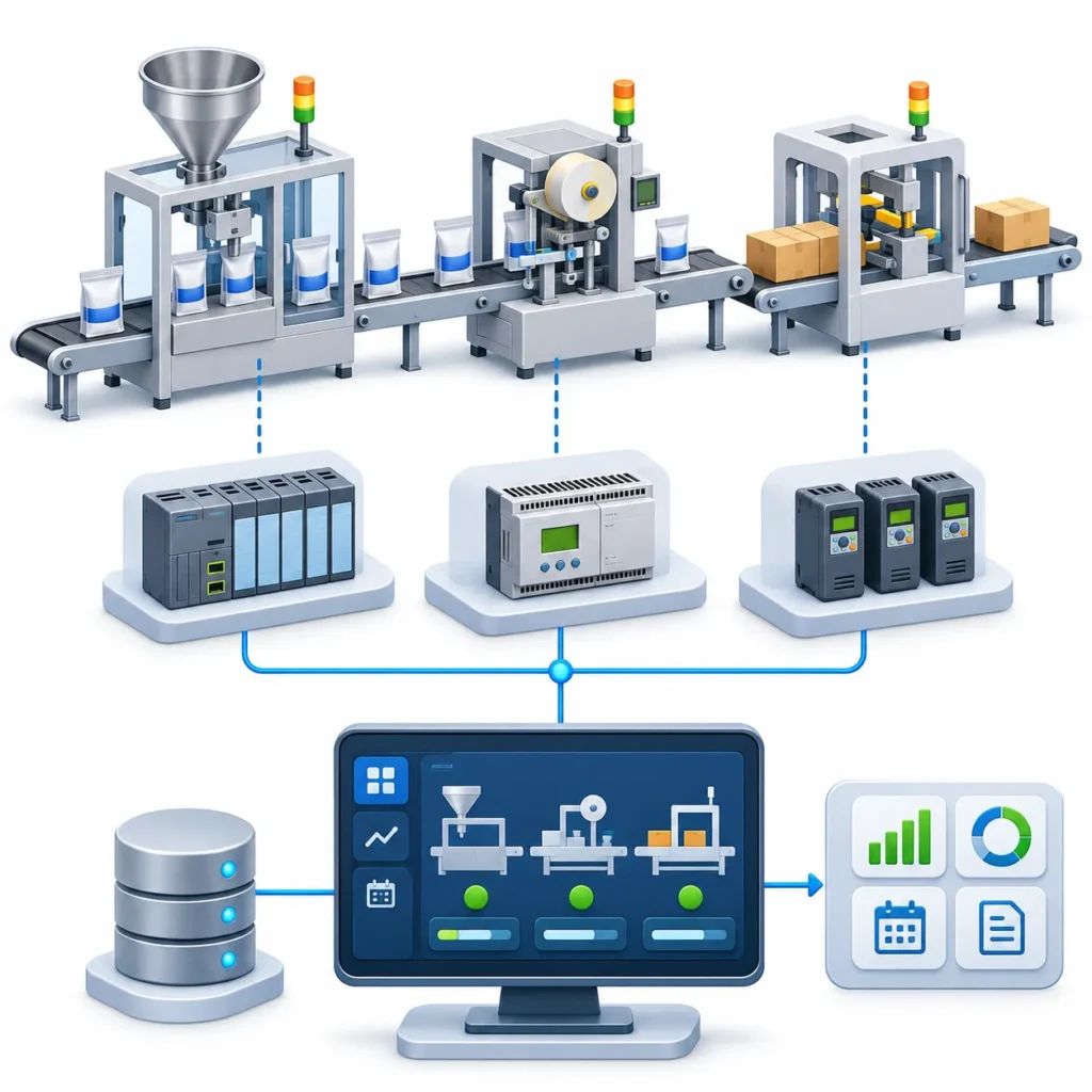
Example: Packaging Line with Mixed Legacy Controllers
A packaging plant runs a filler controlled by an SLC 5/05, a labeler on a MicroLogix 1400 and several drives reachable over Modbus TCP. Operators currently write down downtime on paper at shift end.
The team inventories each controller, takes program backups and confirms that all three expose Ethernet. They create Allen-Bradley and Modbus device connections in an Ignition Gateway placed in the OT network, with write access disabled. Tags cover run state, fault codes, good counts and reject counts, organized in UDTs per machine.
The result is a live view of machine state and counts for each line. Because the data now sits in Ignition’s tag system, an MES or reporting layer can later use the same tags for downtime and order tracking, without touching the PLC programs.
Benefits
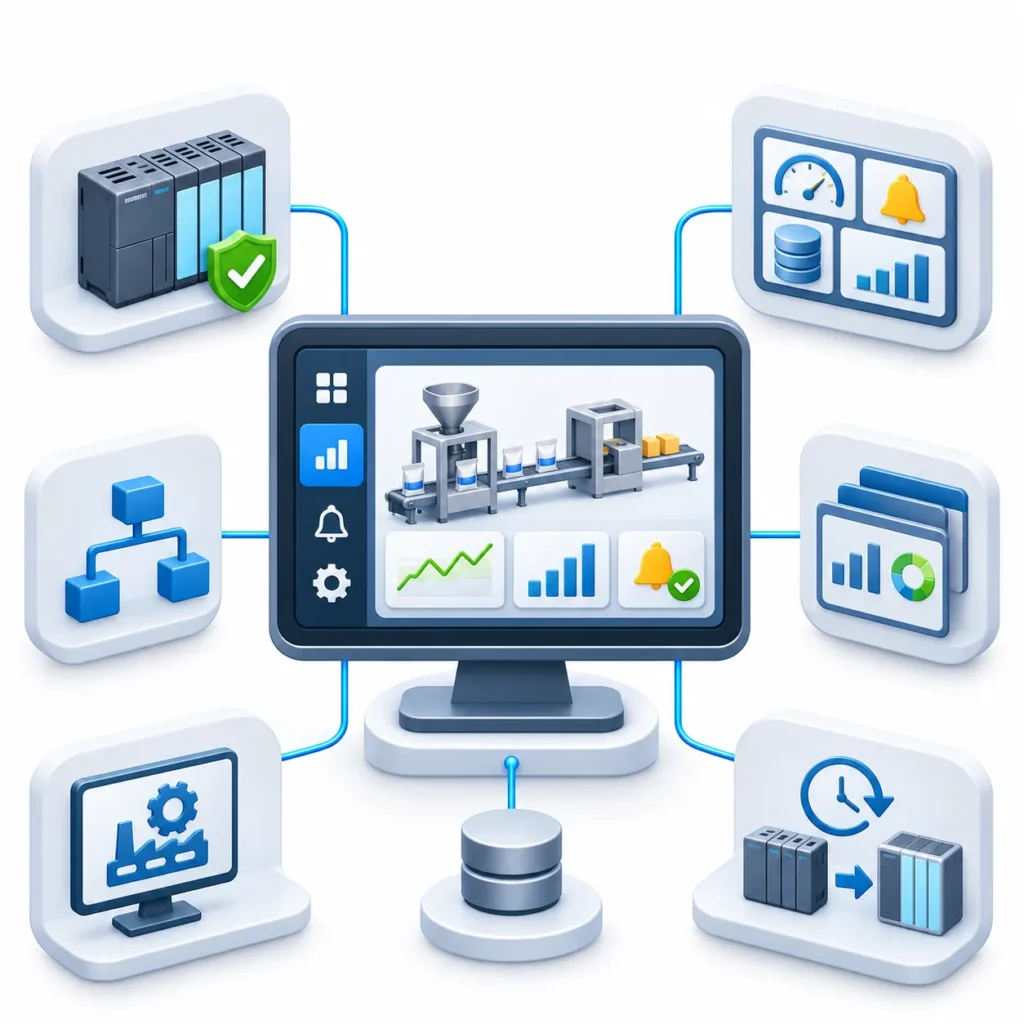
- Visibility into older machines without rewriting validated control logic
- One platform for screens, alarms, history and reporting across mixed brands
- A vendor-neutral OPC UA layer that decouples screens from controller hardware
- A path toward MES and analytics built on the same tags
- A practical staging step before any future controller replacement
Challenges
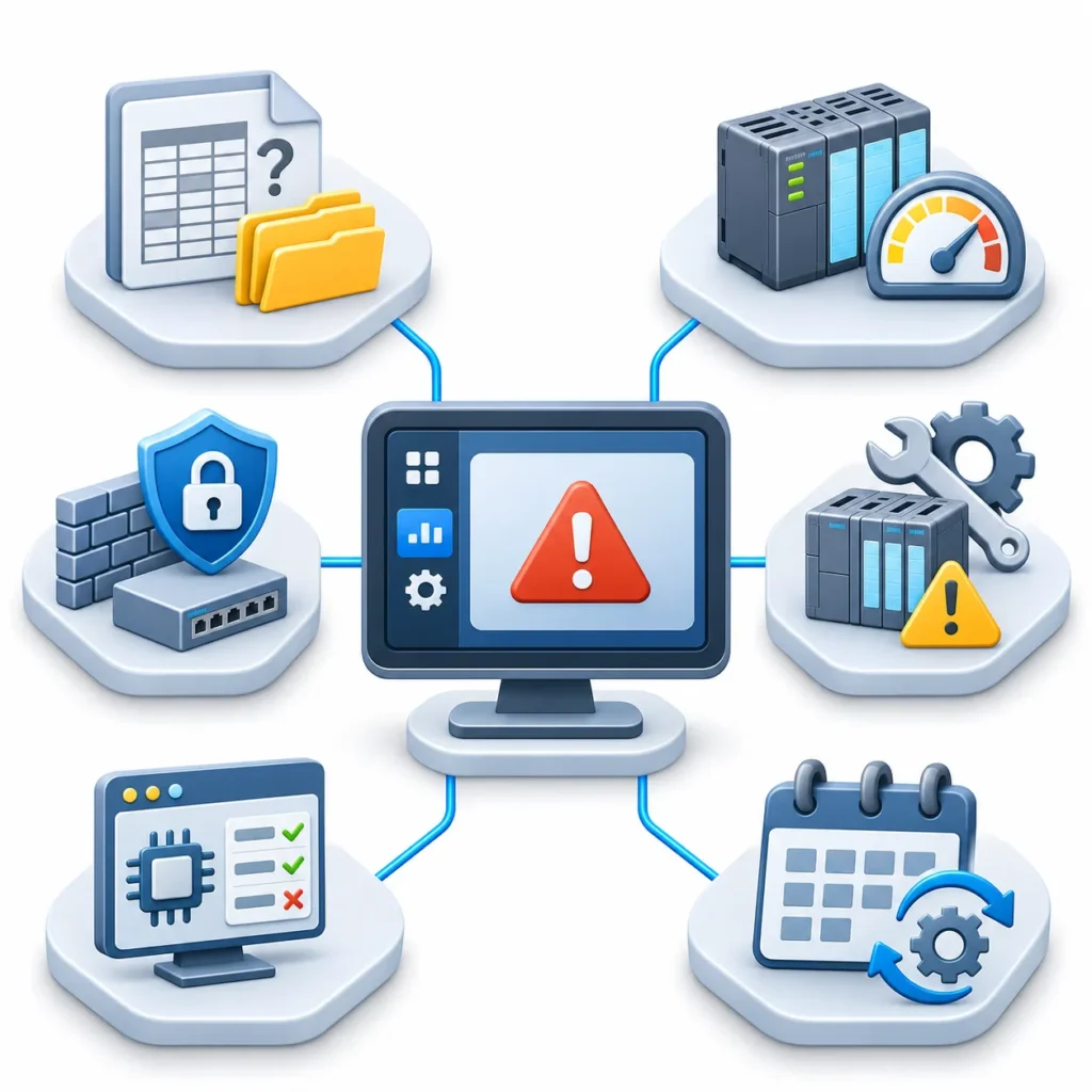
- Addressing and documentation gaps. Missing data maps make tag building slow.
- Limited CPU and communication capacity. Aggressive polling can hurt older controllers.
- Weak native security. Network segmentation and access control must compensate.
- Hardware obsolescence. Wrapping a controller does not make it any easier to repair or source parts for.
- Driver and firmware limits. Some data types or processors are unsupported, as in the PLC-5 ASCII limitation.
- Ongoing ownership. Someone must maintain the tag register, the Gateway and its certificates.
When Wrapping a Legacy PLC Is Not the Right Answer
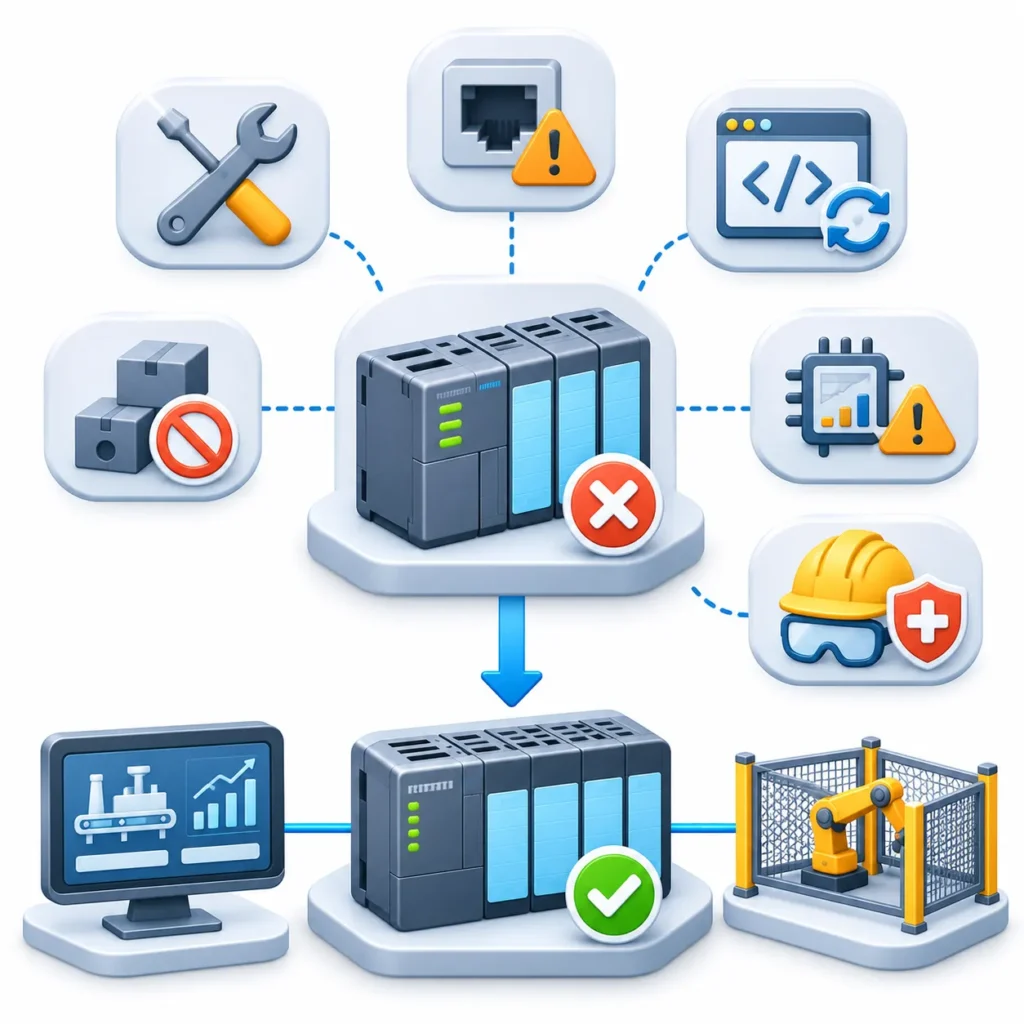
Connecting a legacy PLC is not always appropriate. Consider a migration plan instead when the controller cannot be repaired or sourced, when its communication ports are unreliable, when the control logic itself needs rework, or when the machine needs capabilities the old CPU cannot provide. SCADA is also not a substitute for a safety system: supervisory commands should never be the only protection for people or equipment.
Implementation Checklist
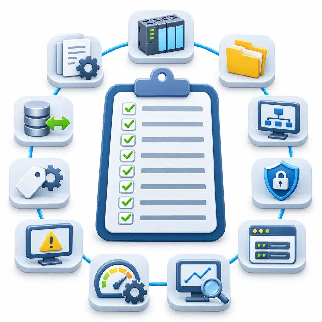
- Controller model, firmware and ports documented
- Program backup stored and address map available
- Driver or OPC UA path selected and confirmed against the vendor documentation
- Network zone, firewall rules and access roles approved
- Device connection created in read-only mode
- Tags built with consistent naming, units and scaling
- Values verified against the PLC online
- Failure behavior and tag quality tested
- Polling rates reviewed against controller load
- Write access enabled selectively, with approval
Conclusion
Connecting a legacy PLC to Ignition is mostly an exercise in discipline rather than technology. The driver choice is usually straightforward once the exact model, firmware and port are known; the harder work is documenting addresses, protecting the network, and proving that every tag matches what the controller really holds. Done that way, SCADA adds visibility and a clean data foundation without disturbing validated control logic. It does not extend the life of failing hardware or replace safety systems. For plants starting this work, the first step is usually to inventory the controllers, confirm available interfaces and map the data worth collecting before choosing a connection path, which is also where INGSOL would begin a brownfield integration.
Contact our Ignition SCADA specialists directly:
Email: sales@ingsol.com
Phone (India): +91 95608 11774
Phone (US): +1 347 570 2629
Our engineers will review your current setup and outline a practical upgrade path built for your plant.